Development of Superconducting Accelerator Magnets at JINR
 , P. G. Akishin, A.V. Butenko,
A. V. Bychkov, G. L. Kuznetsov,
M. S. Novikov, E. V. Sergeeva,
G. V. Trubnikov, E. S. Fischer,, and
A. V. Shemchuk
, P. G. Akishin, A.V. Butenko,
A. V. Bychkov, G. L. Kuznetsov,
M. S. Novikov, E. V. Sergeeva,
G. V. Trubnikov, E. S. Fischer,, and
A. V. Shemchuk
Joint Institute for Nuclear Research, Dubna, Russia
Abstract
The article presents an overview of the work carried out at the Joint Institute for Nuclear Research in Dubna since the early 1970s aimed at creating superconducting (SC) magnets for charged particle accelerators. The specified studies made it possible to build the world's first SC heavy-ion fast-cycling synchrotron — the Nuclotron; magnets for the SIS100 synchrotron of the FAIR project; magnetic systems of the SC Booster and collider of the NICA complex. It also resulted in a development of SC winding for magnet of the medical cyclotron for proton therapy MSC-230, a model magnet for the Chinese HIAF collider project with a record (up to 10 T/s) rate of magnetic field change, a 3-MJ energy storage device based on high-temperature superconductor (HTS), and a concept of magnets for the New Nuclotron made of HTS material for operation at a winding temperature of about 50 K.
Keywords: superconducting magnets, particle accelerators, energy storage devices, high-temperature superconductivity, medical cyclotron
1. Introduction
In the early 1970s, due to the need to conduct research in the field of relativistic nuclear physics, on the initiative of Academician A.M.Baldin, the Director of the Laboratory of High Energies\(^1\) (LHE) of JINR, a proposal was made to replace the magnetic system of the Synchrophasotron with a new, superconducting (SC) one. In 1974, a conceptual design report "Nuclotron — an accelerator complex of relativistic nuclei" was published [1]. The first two prototype dipoles SPD-2 and SPD-3 had a \(\cos\theta\) type winding with field of about 4 T formed by windings and cooled in a bath of boiling helium. In 1974, modeling of SC magnets with an iron yoke was initiated by I.A.Shelayev at LHE. The dipoles were cooled by immersion into liquid helium. These were the magnets: SKD-74, SKD-55, B1 and B2. Such magnets were significantly simpler and cheaper to manufacture but had a limitation on the maximum field of about 2 T and a non-optimal cryostat. In 1978, A.A.Smirnov proposed switching from a double twisted cable (Rutherford-type) to a tubular one (hollow). In this case, an effective heat transfer from superconductor to helium is supported by an absence of electrical insulation on its way [2,3]. The first magnet made of tubular superconductor was manufactured and tested in 1979. It was a prototype of the Nuclotron-type magnets.
In the 2010s, the JINR Member States initiated an extension of the Nuclotron complex to be based on the SC magnets. The extension had to include the heavy-ion linac, the Booster synchrotron and the low-energy collider. The R&D work began at VBLHEP under the leadership of H.G.Khodzhibagiyan to modernize the design of the Nuclotron-type magnets, create a unique factory for assembling and testing superconducting magnets. Later, a pioneer work on the use of high-temperature superconductors (HTS) for rapid-cycling magnets and solenoids has been started. All this opened unique opportunities at JINR for the development of the most advanced energy-efficient superconducting magnets. This review discusses current JINR developments demonstrating record-breaking parameters, as well as prospects for the development of SC and HTS technologies for other accelerators.
2. Nuclotron-type magnet
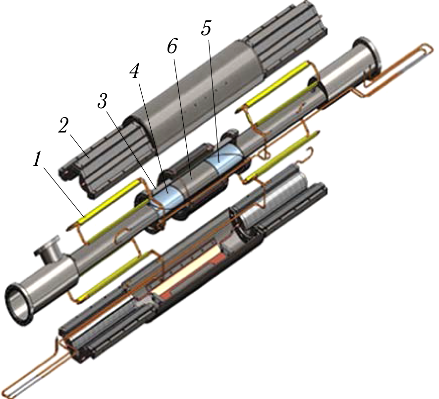
The first stage of development of SC accelerator magnets at JINR began in 1972 and was completed in 1993 with the commissioning of the world's first SC heavy-ion accelerator, the Nuclotron [4]. At this stage, a cable was developed that was called the Nuclotron-type cable (see Figure 1).
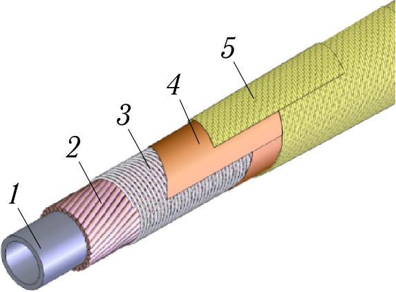
Figure 1. Nuclotron-type cable: 1 — cooling tube; 2 — superconducting wire; 3 — Ni–Cr bandage wire; 4 — polyimide tape (Kapton); 5 — glass tape impregnated with hot-curing epoxy compound.
The Nb–Ti alloy SC wires are spirally wound on a cooling tube made of cupronickel. To ensure good thermal contact, the SC wires are pressed to the cooling tube using a Ni–Cr alloy bandage wire. The cable has electrical insulation made of two layers of polyimide and two layers of glass tape impregnated with epoxy compound. The use of such a cable in accelerator magnets allows one to (1) abandon the helium vessel of the cryostat, (2) reduce the amount of helium in the magnet and, consequently, increase safety in case of helium eruption due to quench, (3) simplify access to the magnet in the cryostat and the beam chamber, and (4) operate with high rate of the magnetic field change. 2 shows the dependences of the critical current change on the magnetic field rate for the Rutherford-type and Nuclotron-type cables.
To cool the cable, a two-phase (boiling) helium flow was chosen as the cooling liquid. That provided a lower cooling temperature compared to supercritical (liquid) helium. The choice of two-phase helium led to a choice of parallel helium supply to the magnets. That was new in the world practice at the time. The reliability of the magnets with a parallel helium cooling system was experimentally confirmed at VBLHEP in the entire range of vapor content from 0 to 1 [5].
Figure 3 shows the cross-sections of a dipole (left) and a quadrupole (right) of the Nuclotron. The Nuclotron accelerator was launched in 1993 and is successfully operating to this day. During its operation, the Nuclotron has experienced more than 60 cycles of cooling to the liquid helium temperature with subsequent warming to the room temperature and several tens of millions of cycles of magnet excitation with current of up to 6 kA [6].
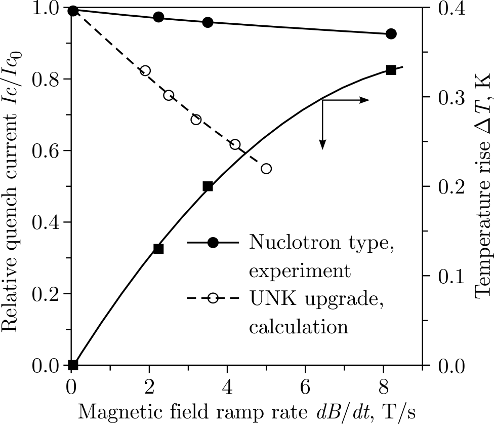
Figure 2. Dependence of the degree of degradation of the critical current on the magnetic field rate.
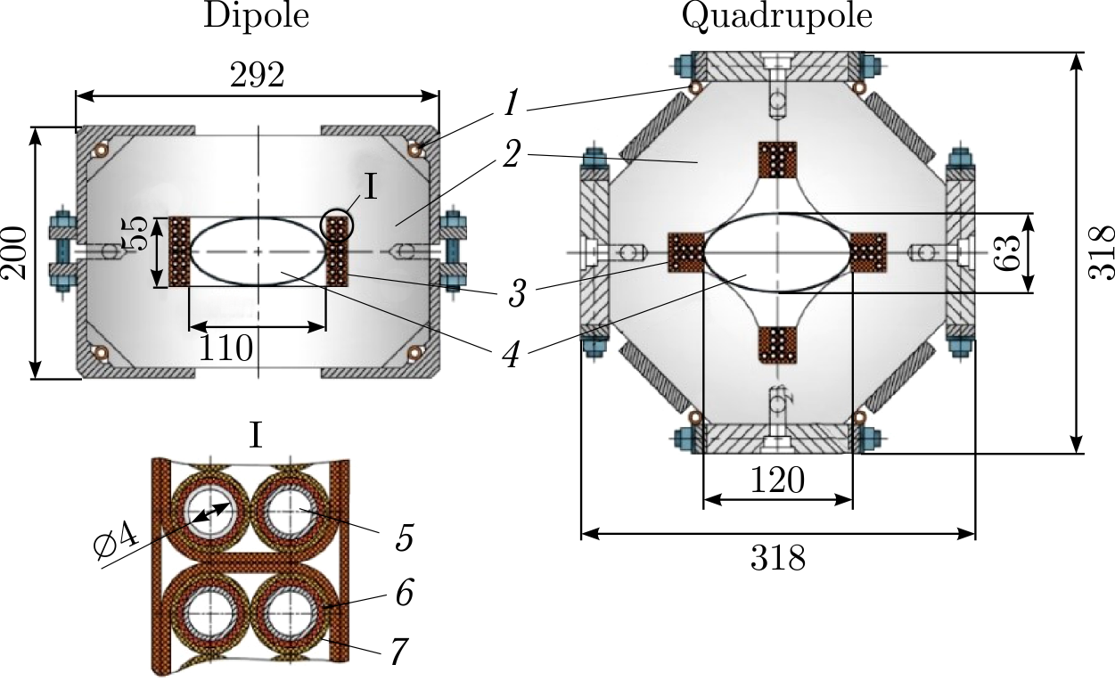
Figure 3. Cross-sections of dipole (left) and quadrupole (right) of the Nuclotron. 1 — cooling tube of the iron yoke; 2 — magnet yoke; 3 — winding; 4 — beam chamber; 5 — cooling tube; 6 — SC wire; 7 — electrical insulation.
3. SIS100 magnet
The second stage of development of SC accelerator magnets at JINR began in 1999 in connection with the request of GSI, Darmstadt, to JINR to participate in the joint development of the SC magnets of the Nuclotron-type for the SIS100 accelerator of the FAIR project [7]. The R&D was completed in 2012 with the launch of serial production of SIS100 magnets [8]. At this stage, the Nuclotron magnet was modernized. Energy losses during operation in a cycle were reduced; the homogeneity of the magnetic field in the aperture was improved; the mechanical and electrical strength of the winding were increased; a single-layer winding and a curved magnet were introduced [9]. Figure 4 shows a comparison of experimental data on the heat generation in the Nuclotron magnet and the SIS100 prototype magnets with various modifications.
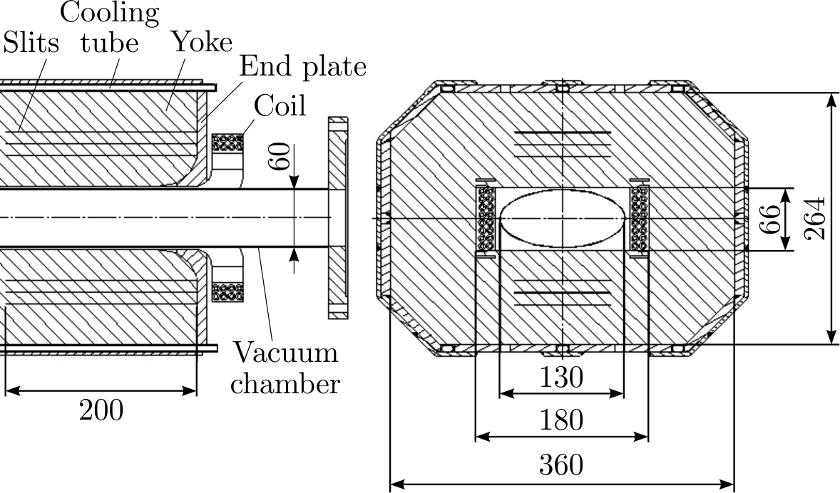
Detailed studies of the losses in yoke have been performed. The measurements of the 3D fringe magnetic field around end parts of the magnet, temperature distribution along the yoke and axial components of the magnetic field enabled considerable reduction of energy losses [10]. Several sources of unaccounted before losses were determined, namely: the yoke end plates and brackets made of ordinary carbon steel 20 mm and 7 mm thick, respectively, and also the end part of the yoke laminations within about 200 mm from the end plates. Finally, a new improved model magnet was constructed and tested [11]. The yoke end plates and brackets were manufactured of stainless steel; narrow slits \((\sim\) 0.1 mm) made with a laser cut machinery were added into the laminations located near the yoke ends (see Figure 5). Also, the magnet coil was modified: (1) end loops were reduced; (2) the new superconducting wire with the filament diameter of 4.2 \(\mu\)m was used for cable manufacturing [12].
Figure 4. Comparison of heat generation in the Nuclotron magnet
and the SIS100 model magnets.
Figure 5. View of the SIS100 model magnet. The six horizontal
slits are introduced to suppress the eddy current effects caused by the
longitudinal field component near the yokes ends.
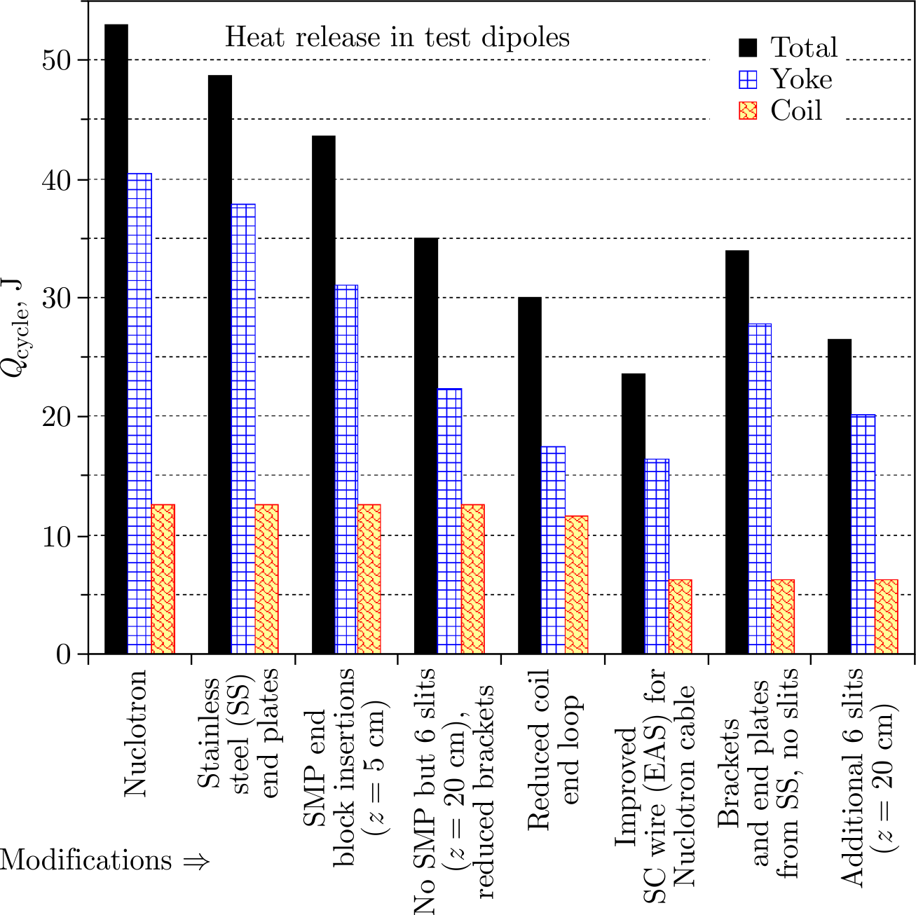
The total dynamic losses in the improved magnet were measured at the level of 24 W, i.e., a factor of 2.2 less in comparison with the original Nuclotron magnet powered with the same reference cycle [13].
The use of the modified Nuclotron-type magnets in the fast-cycling heavy-ion synchrotron SIS100 of the FAIR complex should provide considerable saving on the electricity bill compared to the "warm" version of magnets. This gain is expected to be more significant with time due to expected increase of electricity cost in the future.
The magnetic field quality within the usable dipole aperture of 110 × 55 mm was improved to be better than \(\pm \,6\cdot 10^{-4}\) optimizing the 2D geometry of the lamination [14]. Negative shims were used (see Figure 6).
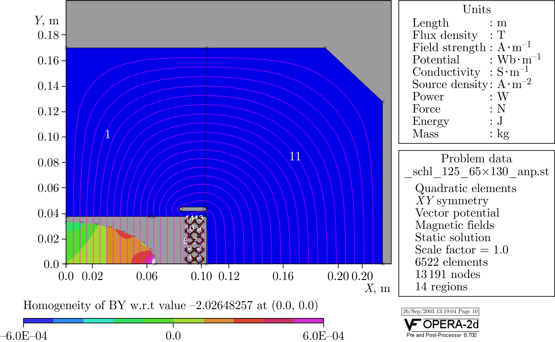
Figure 6. Magnetic field distribution in the model SIS100 magnet with negative shims.
In addition, alternative technologies were developed to enhance the geometrical precision of the cable positioning and the mechanical stability of the coil adding the textured fiberglass (G11) structures into the coil design (see Figure 7) [15].
4. NICA magnets
The third stage of development of SC accelerator magnets at JINR began in 2010. It was initiated by the decision to build the NICA accelerator-collider complex [16] at JINR. Presently, NICA, which is created as an international project, is in the final stage of its construction. The facility is aimed at providing collider experiments with heavy ions (up to bismuth) in the center of mass energy, \(\sqrt s\), from 4 to 11 GeV/u. It the top energy, its average luminosity is expected to exceed \(1\cdot 10^{27}\) cm\(^{-2}\) s\(^{-1}\) for Au\(^{79+}\). Collision experiments with polarized deuterons and protons are also foreseen at the second stage of collider operation. The facility includes two injector chains. The first one, operating with heavy ions, starts at the KRION ion source, then goes through the heavy-ion linac, a recently built superconducting Booster synchrotron and finally through the Nuclotron. It can accelerate heavy ions to about 4 GeV/u. The second chain starts at the polarized source (producing protons or deuterium), then goes through the LU-20 linac and the Nuclotron. For both chains, the beams can be slowly extracted and directed to the fixed-target experiments, or, after one turn extraction, directed to the collider consisting of two rings, each 503 m in circumference.
Figure 7. Coil support structure.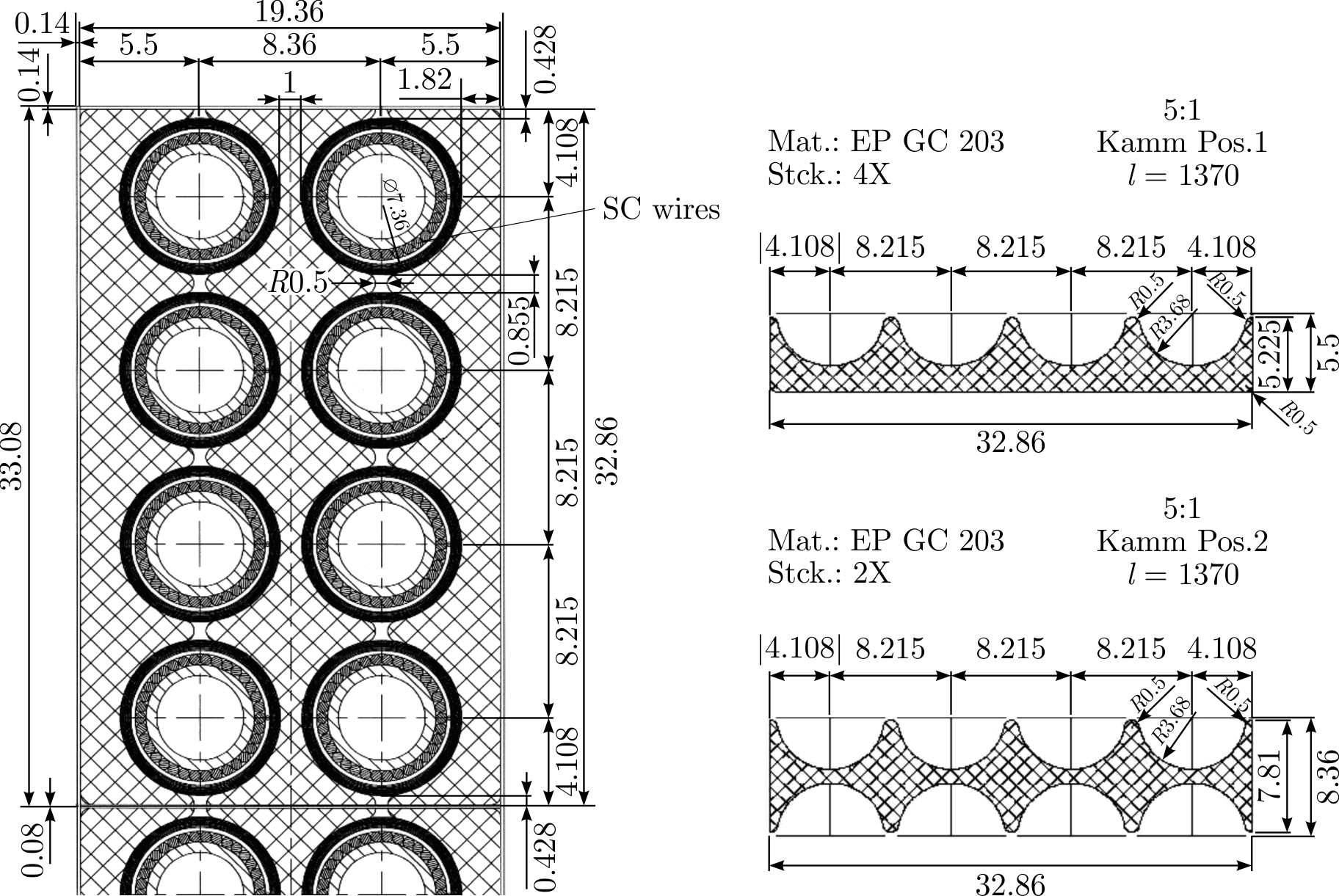
The modified Nuclotron magnets were taken as the basis for the magnetic system of both the NICA Booster and the collider. For the NICA Booster, a half-period includes two single-layer dipoles with a bending radius of about 14 m, a quadrupole doublet and a corrector block located between the lenses (see Figures 8 and 9) [17,18].
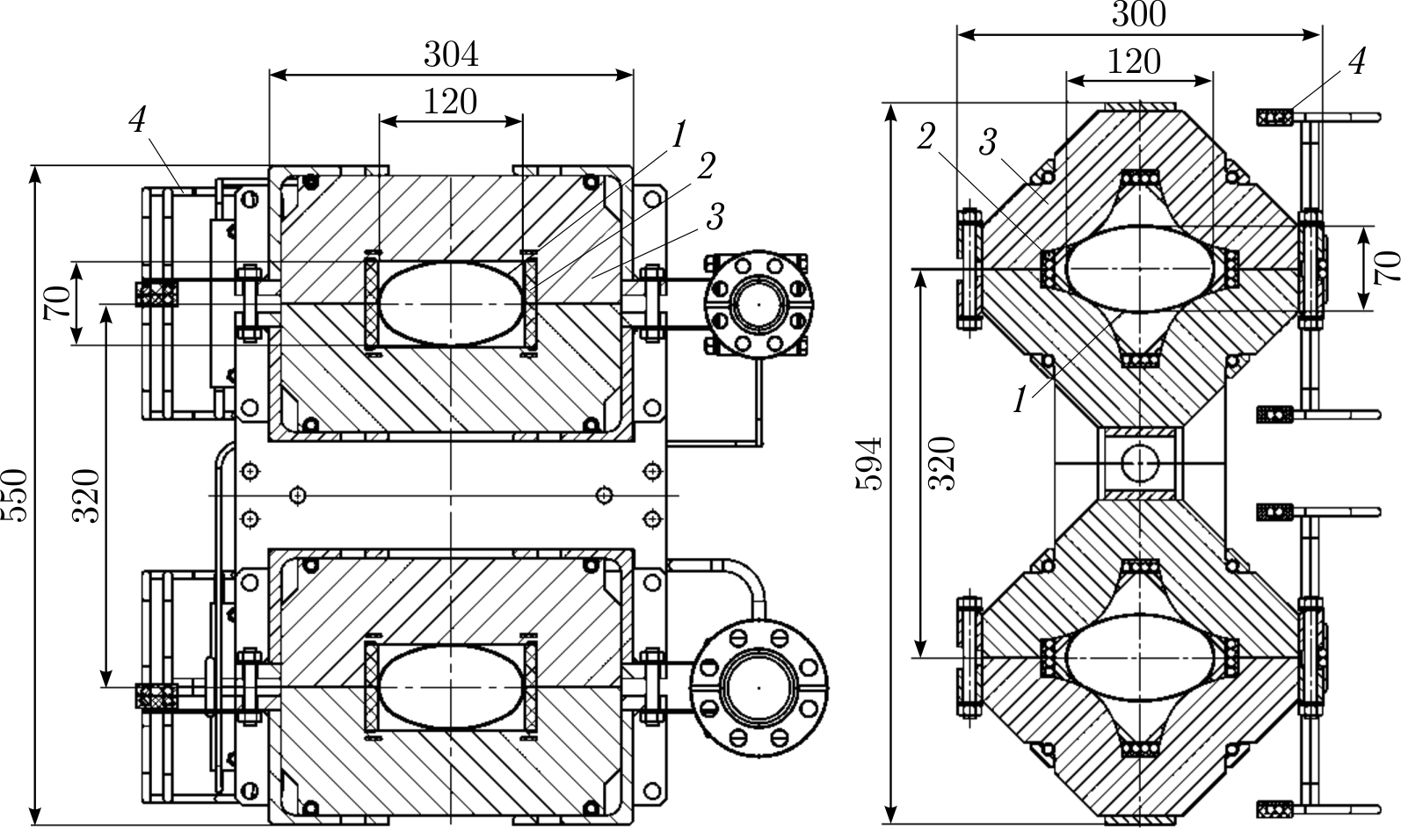
Figure 10. Cross-section view of the dipole (left) and quadrupole (right) for the NICA collider: 1 — beam pipe; 2 — SC coil; 3 — iron yoke; 4 — bus-bars.
For the NICA collider, two-aperture dipoles and quadrupoles were developed (see Figure 10) [19]. All magnets are split into few separate circuits and connected serially within each circuit. To fulfill the requirements of collider beam optics, the quadrupoles of the straight lines have different lengths.
Main characteristics of the Booster and collider magnets are presented in Tables 1 and 2.
| Dipole | Quadrupole | |
|---|---|---|
| Number of magnets | 40 | 48 |
| Max. magnetic field / gradient | 1.8 T | 21.5 T/m |
| Effective magnetic length | 2.2 m | 0.47 m |
| Beam pipe aperture, h/v | 128 mm / 65 mm | 128 mm / 65 mm |
| Radius of curvature | 14.09 m | – |
| Overall weight | 1030 kg | 110 kg |
The NICA Booster was successfully commissioned in late 2020 [20,21]. Commissioning of the NICA collider will start in the first half of 2025.
| Dipole | Quadrupole | |
|---|---|---|
| Number of magnets | \(80 + 8^a\) | \(86 + 12^b\) |
| Max. magnetic field / gradient | 1.8 T | 23.1 T/m |
| Effective magnetic length | 1.94 m | 0.47 m |
| Beam pipe aperture, h/v | 120 mm / 70 mm | |
| Distance between beams | 320 mm | |
| Overall weight | 1670 kg | 240 kg |
\(^{a}\) 4 single aperture and 4 double aperture vertically bending dipoles
required for bringing together and separating beams in the interaction
points.
\(^{b}\) 12 single aperture quadrupoles located around two interaction
points.
5. Superconducting magnet of the cyclotron MSC-230
The fourth stage of development of SC accelerator magnets at JINR began in 2022 in connection with the decision to develop and manufacture, together with JSC "D.V. Efremov Institute of Electrophysical Apparatus", a cyclotron complex based on the MSC-230 superconducting cyclotron for proton beam therapy at JINR.
The MSC-230 magnet consists of a superconducting winding and an iron yoke. The technology using a tubular composite superconducting cable, proposed at VBLHEP and well proven in the magnets of the Nuclotron synchrotron, was chosen as the basis for manufacturing the winding. VBLHEP has a base for producing such a cable, which only requires upgrading the existing equipment.
The magnet winding with an internal diameter of 2560 m consists of two coils, each about 90 mm high, located at a distance of 140 mm from each other and surrounded by a heat shield and a vacuum casing of the cryostat (see Figure 11). Each coil has 281 kA ⋅ turns of tubular superconducting cable and is split into 3 sections. The main characteristics of the cable and superconducting wires are given in Table 3.
The coil is wound on a stainless steel mandrel. Profiled copper strips are placed on top and bottom of each coil layer. These strips required to fill the voids between the turns. Between the winding layers, winding heaters are located, which are necessary to protect against overheating due to quench when the winding transits from the superconducting to the normal state. The winding consists of 6 sections, three in each coil. A bandage of stainless tape is wound around the coil. After winding, the coil is heat treated to polymerize the epoxy compound. The coils are connected to each other on the mandrel. In this case, the helium cooling communications of the winding are connected, as well as electrical connections between the sections. The main characteristics of the magnet winding are given in Table 4.
The maximum operating temperature of the winding is 5.5 K, the nominal flow rate of liquid helium through the winding is about 0.6 g/s. The cold mass of the winding is about 550 kg. The winding is planned to be cooled by a helium refrigerator with a cooling capacity of 6.0 W, which will be installed in the immediate vicinity of MSC-230. The main characteristics of the cooling system are given in Table 5.
External resistance \(R_{e} = 0.509\) Ohm limits the maximum voltage relative to the "ground" during energy evacuation to \(\pm \,250\) V. Shunts divide the winding into 54 parts, 9 in each section. A shunt is electrically connected in parallel to each pair of superconducting wires of the section, which has good thermal contact with the superconducting cable along its entire length, which ensures a high speed of propagation of the normal zone in the winding. The calculated value of the maximum winding temperature as a result of superconductivity breakdown will not exceed 100 K, the evacuation time constant will be about 18 s.
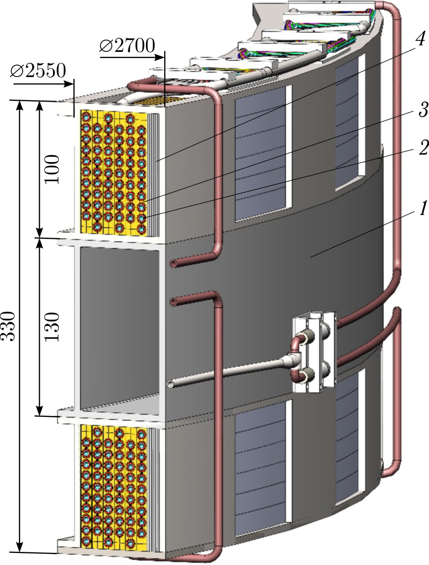
Figure 11. View of the magnet winding of the MSC-230 cyclotron: 1 — spacer between coils; 2 — winding cable; 3 — winding structure; 4 — bandage.
| Cable | ||
|---|---|---|
| Cooling channel diameter | mm | 3.4 |
| Tube material | Cu–Ni | |
| Number of pairs of SC wires | 9 | |
| Outer diameter of cable with insulation | mm | 7.52 |
| Cross-sectional area of copper | mm\(^2\) | 8.37 |
| Cross-sectional area of a superconductor | mm\(^2\) | 1.84 |
| Total length in winding | m | 986.2 |
| SC wire | ||
| Diameter with insulation | mm | 0.9 |
| Superconductor | Nb–Ti/Cu | |
| (Nb–Ti) / Cu — volume ratio | 1 / 4.56 | |
| Superconducting filament diameter | \(\mu\)m | \(\leqslant\) 60 |
| Maximum working current in the wire, \(I_{max}\) | A | 245.5 |
| Critical current at 2.2 T and 4.8 K | A | \(\geqslant\) 470 |
| Total length of SC wire in winding | m | 19 100 |
The calculated value of heat influx to the winding at 5 K is about 4 W, heat influx to the thermal screen at 80 K is about 52 W.
| Support cylinder | ||
|---|---|---|
| Length | m | 0.28 |
| Inner diameter | m | 2.55 |
| Outer diameter | m | 2.56 |
| Material | Steel 12X18H10T | |
| Winding | ||
| Nominal magnetic field in the aperture, \(B_0\) | T | 2.0 |
| Maximum magnetic field in the winding | T | 1.95 |
| Total length of a set of 2 coils and a gap | m | 0.26 |
| Inner diameter | m | 2.563 |
| Outer diameter | m | 2.669 |
| Number of layers | 6 | |
| Number of winding sections | 6 | |
| Number of turns of cable | \( 6 \times 10 \times 2 \) | |
| Maximum working current (a pair of wires), \(I_{max}\) | A | 491 |
| Inductance | H | 27.4 |
| Stored energy at \(I_{max}\), E | MJ | 3.3 |
| Volume of liquid helium in the winding | I | 7.0 |
| Cold mass at 5 K | ||
|---|---|---|
| Conductor | kg | 91.6 |
| Cooling tube, \(M_2\) | kg | 66.3 |
| Copper inserts in the voids between the turns of the winding, \(M_3\) | kg | 193.7 |
| Electric shunts — heaters, \(M_4\) | kg | 14.0 |
| Stainless steel bandage, \(M_5\) | kg | 119 |
| Inner winding mandrel, \(M_6\) | kg | 65.0 |
| Total | kg | 550 |
| Cooling | ||
| Method: Forced circulation of supercritical helium | 2 | |
| Maximum operating temperature, \(T_0\) | K | 5.5 |
| Thermal load under operating conditions | W | \( \leqslant \) 5 |
| Nominal mass flow rate of helium | g/s | 0.6 |
| Number of parallel cooling channels | 2 | |
| Nominal pressure drop in the channel | kPa | 18 |
| Permissible pressure in the cooling channel | MPa | 10 |
| Cooling time from 300 to 4.8 K, \( \frac{dT}{dt} \leqslant 3 \ \text{K/h} \) | hour | \( \leqslant \) 200 |
The basic diagram of winding cooling is shown in Figure 12.
The estimated cooling capacity of the cryogenic unit is 6 W at 5 K. A 30-bar membrane-type compressor with a capacity of 14 Nm\(^{3}\) /h is provided for the cryogenic system.
The first stage of preliminary cooling of the refrigerator is provided by the first stages of two OPERATION 2 cryocoolers with a capacity of 45 W at 77 K each. They also cool the thermal screen of the refrigerator cryostat. The second stage of preliminary cooling of the refrigerator is provided by the second stages of the same two OPERATION 2 cryocoolers with a capacity of 14 W at 10 K each. The final stage of cooling operates according to the throttling principle. A regulating valve is installed at the outlet of helium from the cooling channels of the solenoid. The valve is designed to adjust the helium pressure in the magnet winding. The heat flux coming from the current leads is removed by an OPERATION 8 cryocooler with a capacity of 67 W at 40 K. The heat flux coming from the winding thermal screen is removed by four TC4188 cryocoolers with a capacity of 15 W at 77 K each, evenly installed on the cryostat cover. As a backup cooling system for the solenoid thermal screen, natural circulation of liquid nitrogen with vapor recondensation in a TC4862 cryocooler is anticipated.
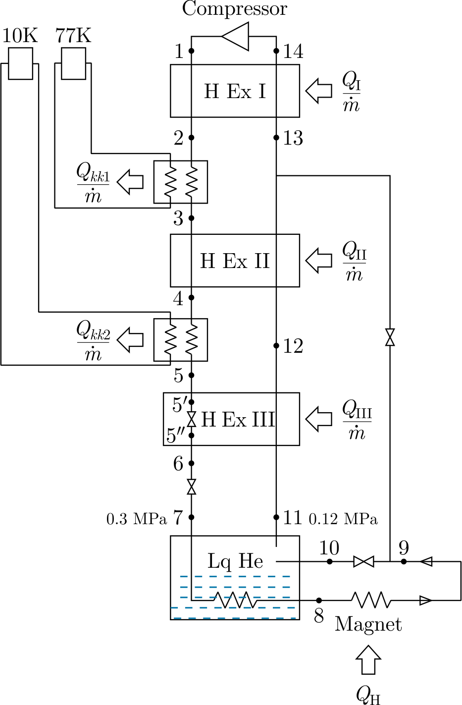
Figure 12. Schematic diagram of the cooling of the magnet winding of MSC-230.
The commissioning of the MSC-230 accelerator is scheduled for 2025.
6. SMES for the NICA power system assignment
NICA Superconducting Magnetic Energy Storage (NICA SMES) is designed at JINR for the NICA power system. It is aimed at the reduction of consumed power and minimization of power grid excitation by reduction of fluctuations of consumed power and removing its reactive part. The system will be used as the main power supply of Booster and Nuclotron magnets [22]. SMES is designed to be part of semiconductor pulse-width modulation power supply developed by LM Invertor company. Additionally to SMES, the power supply uses a capacitor energy storage. This power system can operate with both synchrotrons or any of them alone, using SMES or capacitor storage, or without storages (exchanging both active and reactive power with the power grid). An operation with SMES power convertors enables reducing the consumed power by one or two order of magnitude relative to the reactive power required to feed magnets in an accelerating cycle. The system compensates the resistive losses in feeders and current leads, and the AC losses in SC magnets. The giant reactive power circulates only inside convertors between accelerator magnets and SMES. Consequently, it minimizes disturbances to the power grid and minimizes negative influence on sensitive systems of the NICA complex. The ultimate SMES operating mode with the Booster and the Nuclotron is presented in Figure 13.
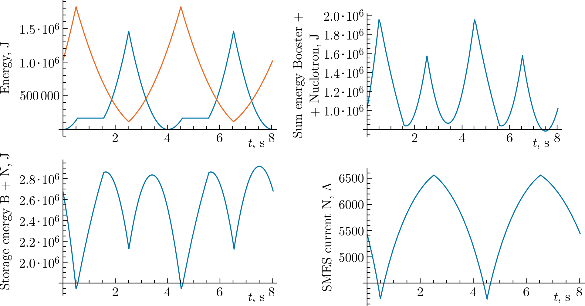
Figure 13. Dependences on time for currents and energies for Booster, Nuclotron and SMES magnets; top left figure: red line — Nuclotron current, blue line — Booster current.
Required SMES energy and current modes are determined by the mode of Nuclotron and Booster operation. If both rings operate, they have the same duration of accelerating cycle but the cycles have different shapes and shifted in time by time required for acceleration in the Booster. Consequently, SMES should store, receive and return of about 2 MJ during approximately 5-s accelerating cycle.
6.1. 3 MJ 2G HTS SMES for the NICA power system design
A solenoid (inside a cryostat) for SMES of the NICA power supply is presented in Figure 14a, and its magnetic field distribution is shown in Figure 14b. The maximum stored energy at current of 6.7 kA is 3 MJ. The maximum magnetic field at the winding is almost 6 T. The magnet may be pulsed with the shortest period of 2 s and the maximum reactive power of about 1 MW. Such fast magnetic field ramp requires the magnet to be made of HTS. That significantly reduces the power required for cooling and, in the case of realistic cooling power, results in better operational stability. Operating temperature of SMES is 30 K due to planned liquid neon cooling.
The solenoid parameters are presented in Table 6. Solenoid height is 0.8 m.
The solenoid will consist of 14 sections (coaxial HTS cable layers) with serial electrical connection and combined serial and parallel LNe connection. The cables of different layers will have different HTS tape quantities which are in proportion to the maximum magnetic field they see. It is done to minimize the HTS cost. The cryostat is designed as a vacuum vessel with LN\(_{2}\) thermal shielding.
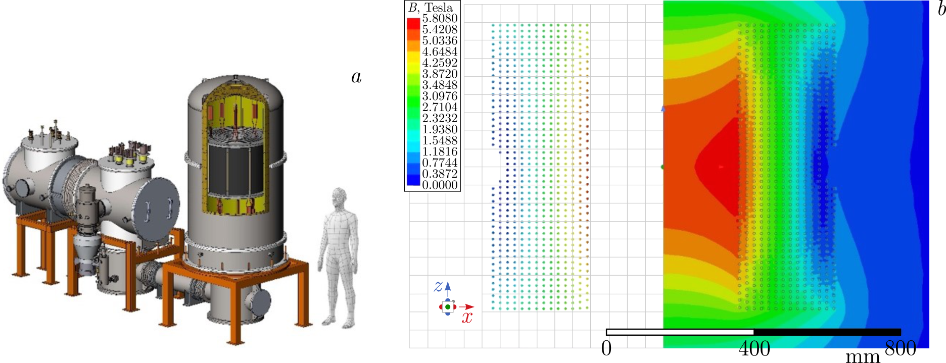
Figure 14. (a) SMES solenoid in the cryostat; (b) magnetic field distribution at the winding.
| Layer | Turn diameter, m | Turns number | Cable length\(^*\), m | HTS tape piece length\(^*\), m | Mag. field, T | HTS tapes number | Brass tapes number | Cable with prepreg diameter, mm | HTS tapes length\(^*\), m |
| 1 | 0.395 | 40 | 51.65 | 61.65 | 5.62 | 32 | 18 | 10.6 | 1972.66 |
| 2 | 0.433 | 46 | 64.59 | 76.59 | 5.22 | 31 | 19 | 10.6 | 2374.27 |
| 3 | 0.471 | 50 | 76.01 | 89.77 | 4.83 | 29 | 21 | 10.6 | 2603.31 |
| 4 | 0.523 | 50 | 84.18 | 99.20 | 4.42 | 27 | 23 | 10.6 | 2678.52 |
| 5 | 0.561 | 50 | 90.15 | 106.10 | 3.98 | 26 | 24 | 10.6 | 2758.58 |
| 6 | 0.599 | 50 | 96.12 | 112.99 | 3.51 | 24 | 26 | 10.6 | 2711.86 |
| 7 | 0.654 | 50 | 104.76 | 122.97 | 3.03 | 23 | 26 | 10.6 | 2828.39 |
| 8 | 0.693 | 50 | 110.89 | 130.05 | 2.78 | 21 | 29 | 10.6 | 2731.04 |
| 9 | 0.748 | 50 | 119.53 | 140.03 | 2.64 | 21 | 29 | 10.6 | 2940.61 |
| 10 | 0.785 | 50 | 125.35 | 146.74 | 2.48 | 20 | 20 | 10.2 | 2934.85 |
| 11 | 0.838 | 50 | 133.67 | 156.36 | 2.32 | 20 | 20 | 10.2 | 3127.18 |
| 12 | 0.875 | 50 | 139.49 | 163.07 | 2.15 | 19 | 21 | 10.2 | 3098.38 |
| 13 | 0.928 | 46 | 136.15 | 159.22 | 1.99 | 18 | 22 | 10.2 | 2865.93 |
| 14 | 0.965 | 40 | 123.30 | 144.38 | 1.81 | 16 | 24 | 10.2 | 2310.14 |
| Length, m | 1455.86 | 37935.72 | |||||||
|---|---|---|---|---|---|---|---|---|---|
| \(30^\circ\) wrapping angle, approximately | |||||||||
6.2. SMES HTS cable design
Operation with high magnetic field rate requires a twisted HTS cable with effective cooling. It is achieved by cooling the tube around which the superconductor is wound — similar to the Nuclotron-type cable developed at JINR more than 35 years ago. HTS cable for SMES is similar to LTS cable of the Nuclotron type but wrapped with several layers of 2G HTS tape instead of one layer of Nb–Ti strands. Such HTS cable is also known as CORCC. The cable design and a part of wrapping process are shown in Figure 15.
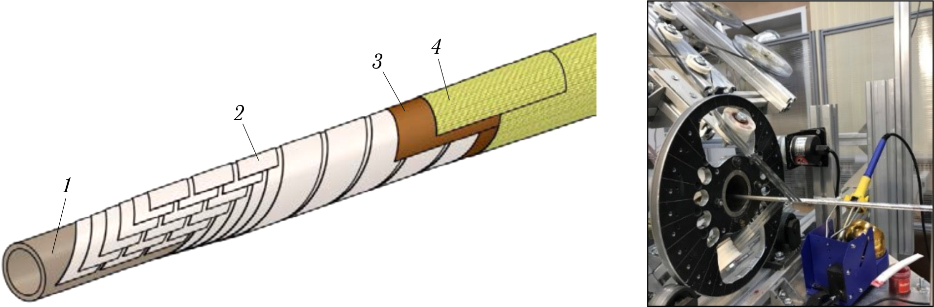
Figure 15. SMES cable structure and photo of cabling process (1 — Cu–Ni alloy tube 8 mm O.D., 6 mm I.D., 2 — HTS tapes 4 mm “high field”, 3 — brass tapes, 4 — prepreg tapes).
The cables will be impregnated with epoxy compound and wrapped around with stabilizing brass tapes and isolating prepreg. The frames of the solenoid are made from G11 fiberglass tubes with rounded spiral grooves for the cables. Stainless steel bandages of each section will be applied to prevent damage from ponderomotive forces.
Neon liquefier with maximum cooling capacity of 500 W at 30 K is under installation now.
6.3. HTS cable and winding machine design
A new cable machine for serial production includes wrapping units for five HTS and one brass tapes. It also has isolating unit, cable impregnating system, tube outlet bobbin, and HTS cable receiving bobbin with a device for solenoid winding. Figure 16 shows pictures of the cable machine which allows us to make an HTS cable and a section of SMES in one pass [23-25].
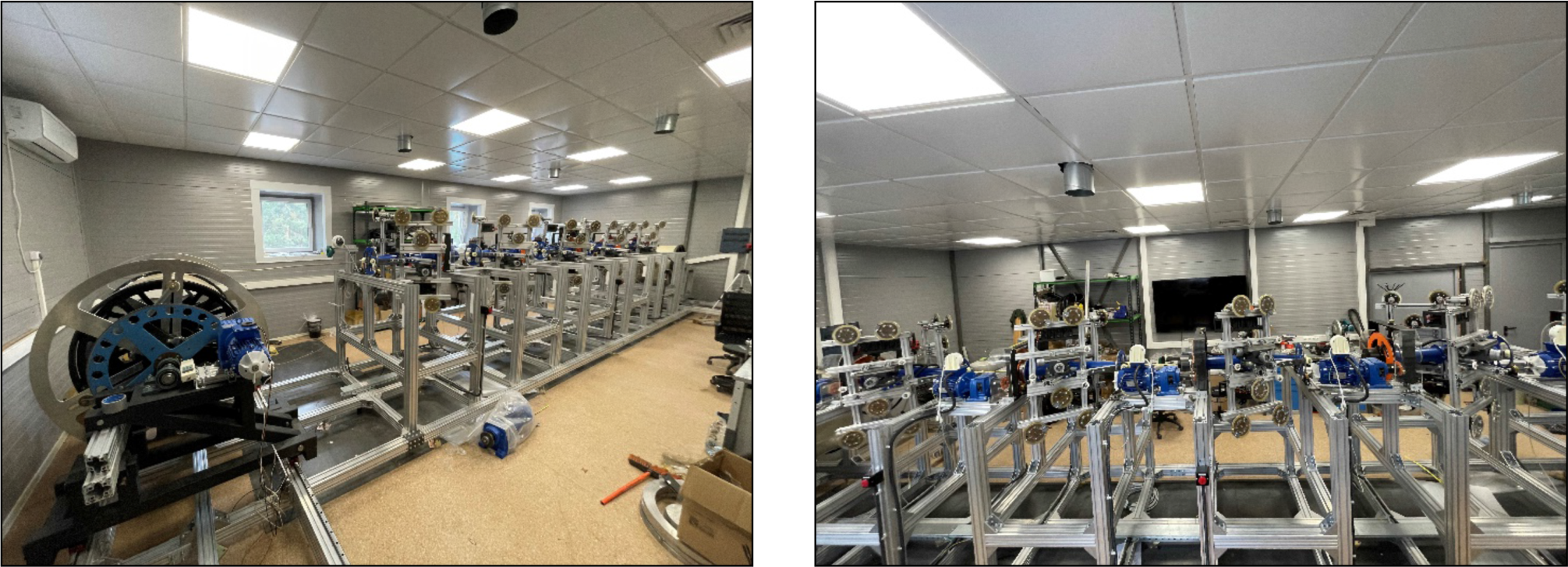
Figure 16. Pictures of the cable/winding machine.
The magnet protection will consist of normal zone detecting system and energy evacuation system with outer evacuating switches and resistors. To reduce evacuation time, the SMES winding is separated into two parts with 2 pairs of HTS current leads.
7. FRDM magnet
The sixth stage of development of SC accelerator magnets at JINR began in 2022 in connection with the decision to develop and manufacture, together with IMP, Lanzhou, a model rapid-cycling magnet for the HIAF project. A demand for high beam intensities of future high-intensity synchrotrons requires fast ramping superconducting dipole magnets (FRDM) with \(dB/dt\) of up to 10 T/s. A FRDM prototype was designed at JINR with the specifications shown in Table 7.
| Parameter | Unit | Value |
| \(L_{eff}\) | m | 1.0 |
| \(BL_{max}\) | T | \(1.6 \sim 1.8\) |
| SC strand diameter | mm | 0.78 |
| Nominal filament diameter | \(\mu\)m | 6 |
| Cu/SC ratio | 1.38 | |
| Twist pitch | mm | 7 |
| Critical current \( I_c \) at 2 T, 4.2 K | A | 900 |
| Cu–Ni cooling tube diameter | mm | \(5 \times 0.5\) |
| Number of strands in the cable | 22 | |
| Cable outer diameter | mm | 7.72 |
| Beam pipe aperture, h/v | mm | 130/85 |
| Iron yoke aperture, h/v | mm | 154/96 |
| Number of coil turns | 12 | |
| Operating current | A | 11 750 |
| Ramp rate | T/s | at least 6 |
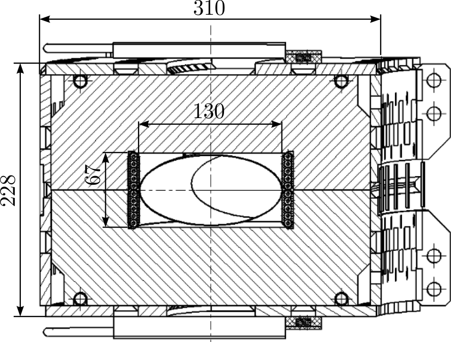
The compact coil design has 12 turns and, consequently, each pole has 6 turns. A slot located above the coil groove is used for improving the field homogeneity. The magnetic field in the center reaches 1.8 T at the operating current of 11\,750 A. Figure 17 illustrates the cross-section of the dipole magnet. The dimension of the iron yoke is \(298\times 240\) mm. The distance between centers of two adjacent cable turns is about 8.0 mm.
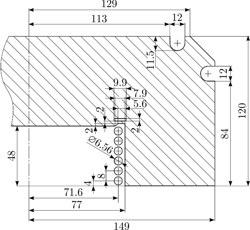
Figure 17. Cross-section view of the FRDM magnet.
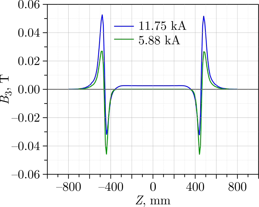
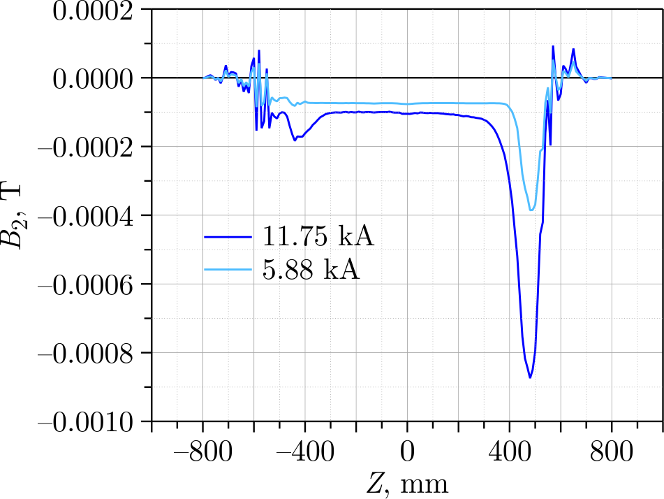
The software OPERA-3D is used for 3D field calculation, the results of which are presented in Table 8. Distribution of the magnetic field harmonics along dipole for operating currents of 11 754 A and 5877 A are shown in Figures 18, 19 and 20.
| \(I = 11\,754\ \mathrm{A}\) | \(I = 5\,877\ \mathrm{A}\) | |||
| Harmonic number | \(\int {B_{n}dl}, T \cdot\) mm | \({10}^{4}\frac{\int {B_{n}dl} }{\int {B_{1}dl} }\) | \(\int {B_{n}dl}, T \cdot\) mm | \({10}^{4}\frac{\int {B_{n}dl} }{\int {B_{1}dl} }\) |
| 1 | 1714.51 | 10\(^4\) | 918.67 | 10\(^4\) |
| 2 | –0.20 | –1.2 | –0.11 | –1.1 |
| 3 | 5.64 | 32.9 | –0.08 | –0.9 |
| 4 | –0.08 | –0.5 | –0.05 | –0.6 |
| 5 | 0.73 | 4.2 | 0.08 | 0.8 |
| 6 | –0.01 | –0.11 | –0.01 | –0.1 |
| 7 | –0.0 | –0.0 | –0.02 | –0.2 |
| 8 | 0.0 | 0.0 | 0.0 | 0.0 |
| 9 | –0.01 | –0.1 | –0.0 | –0.0 |
| 10 | –0.0 | –0.0 | –0.0 | –0.0 |
The FRDM magnet was manufactured (see Figure 21) and successfully tested in September 2024. The main test results are given in Figure 22. The magnet operated stably at a ramp rate of 9.5 T/s and with 1-s cycle duration. The possibility of continuing R&D for the HIAF magnets is being considered with the goal to increase the magnetic field and its ramp rate.
8. New Nuclotron magnet
The seventh stage of development of SC accelerator magnets at JINR began in 2023 in connection with the decision to develop and manufacture new magnets for the Nuclotron upgrade aimed to replace the existing magnetic system. The Nuclotron magnetic system has been in operation at VBLHEP since 1993. It has undergone about 60 cooling/heating cycles from ambient temperature to 4.6 K, several tens of millions of excitation cycles with a current of up to 6 kA, and needs to be replaced in the coming years to ensure long-term uninterrupted operation as part of the NICA complex.
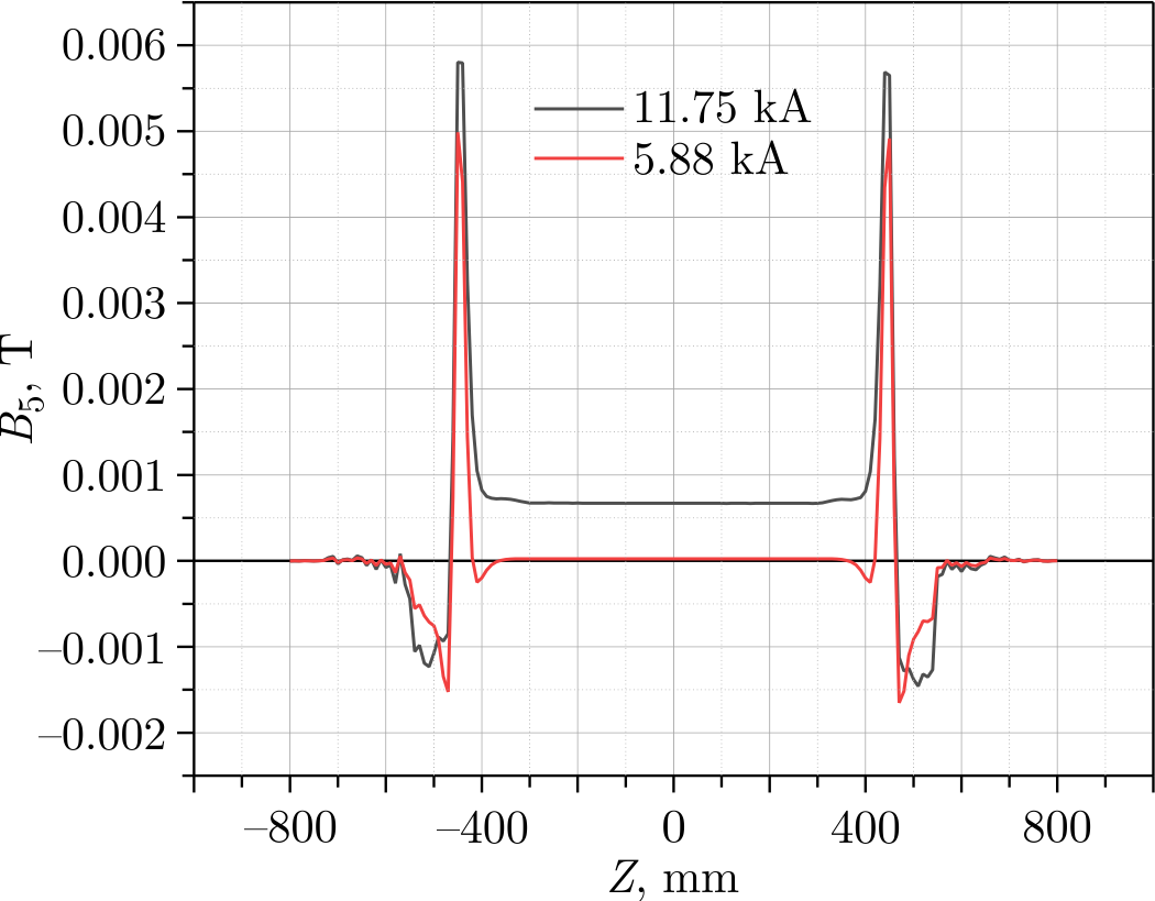
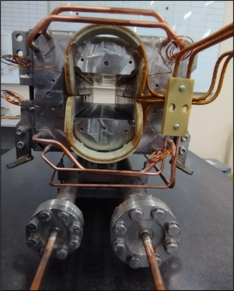
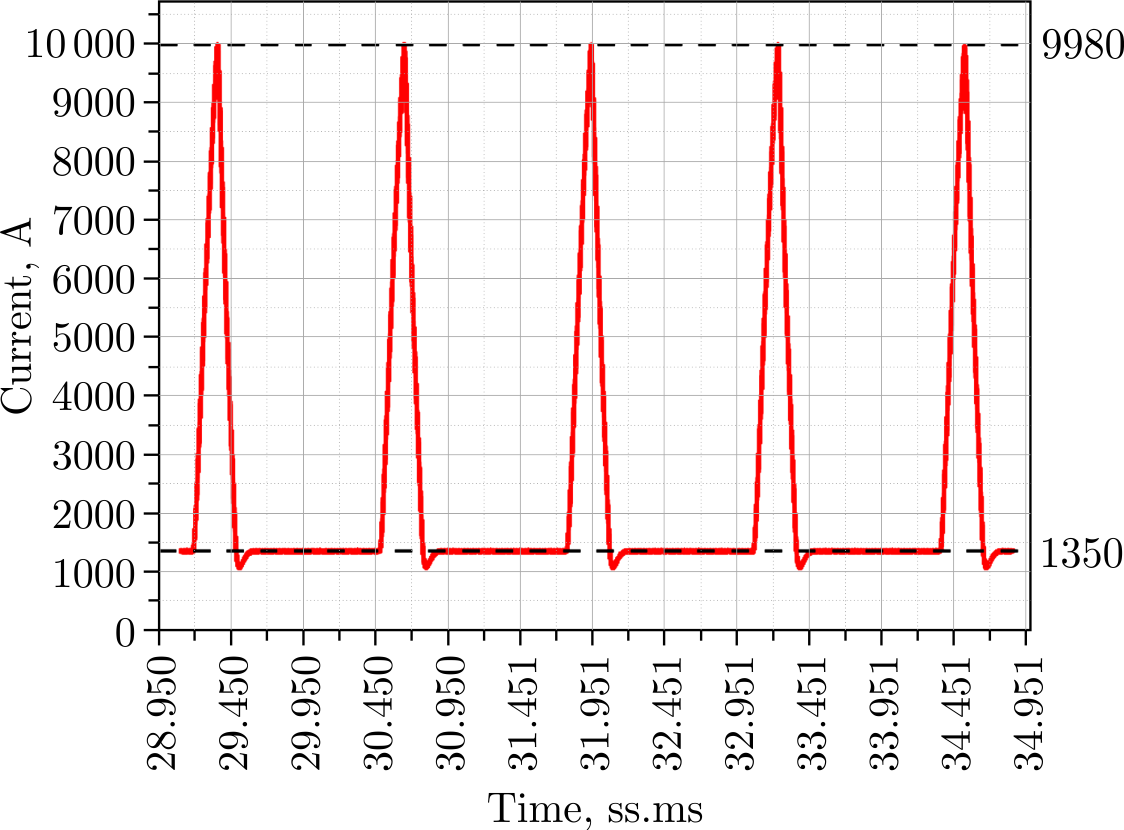
Figure 22. Current cycle No. 12 (\(dB/dt = 9.5 T/s, t_0 = 1 s\)).
An upgrade of the Nuclotron magnetic system has the following goals:
- Optimization of the structure of the accelerator’s magnetic optics;
- The beam optics should include equipment for spin physics research and spin conservation during acceleration;
- Manufacturing the magnet windings from a high-temperature superconductor, which has to reduce operating costs for magnet cooling by several times;
- Usage of curved dipoles will reduce the number of magnets by half and enables us to place additional equipment on the accelerator ring;
- Planned choice of single-layer windings will reduce the cross-section of the magnets.
The magnet windings of the updated Nuclotron will be made of a second-generation high-temperature superconductor of the ReBCO type [26].
It is planned to use an HTS tape from S-Innovations Russian company with a critical current of over 600 A at 30 K in a field of 2 T, 70–80 \(\mu\)m thick, 4 mm wide. A high-current cable is wound from the tapes using a cable machine developed and manufactured at VBLHEP (see Figure 23), which allows one cable manufacturing from 40–50 HTS tapes in one pass.
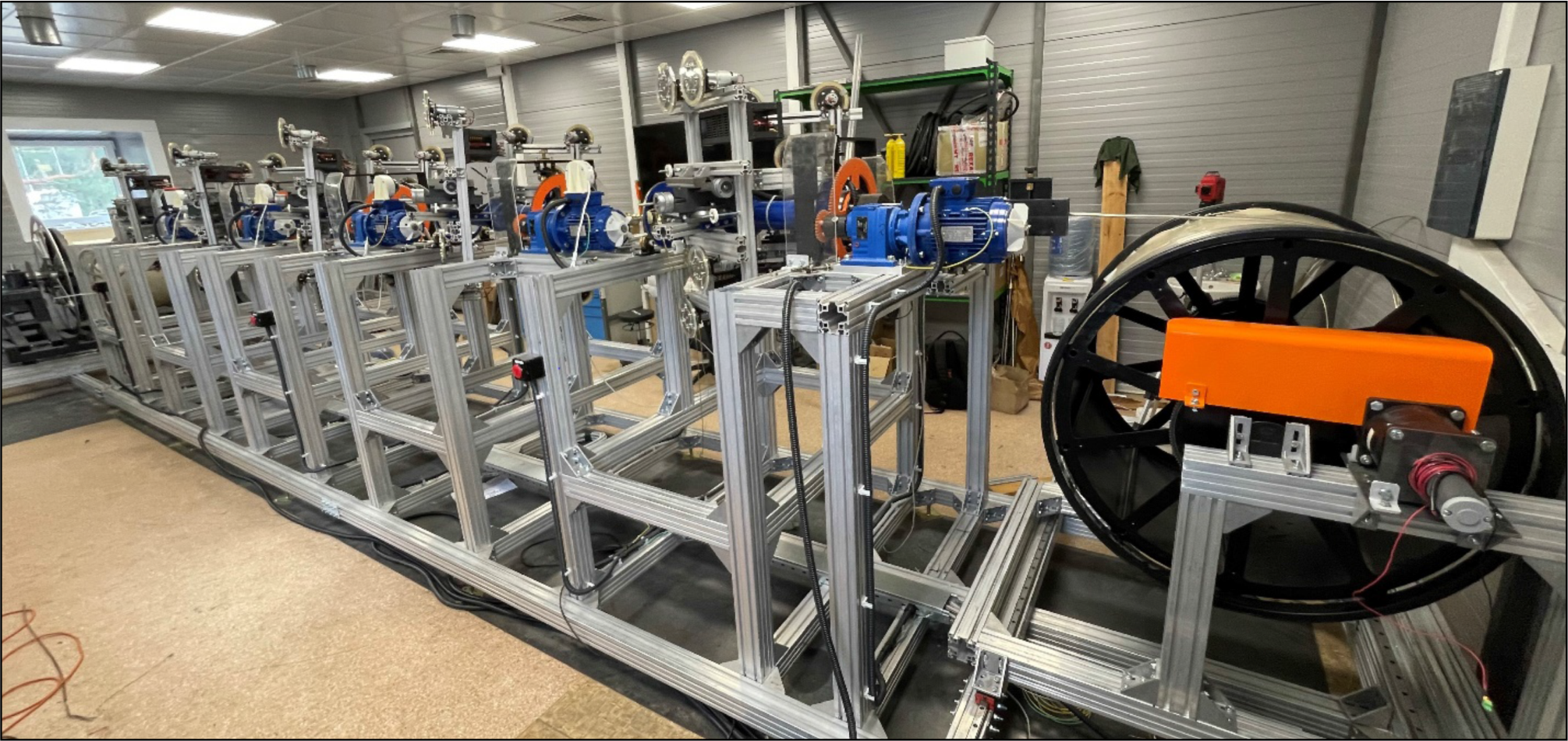
Figure 23. High-current HTS cable winding machine.
The HTS tapes are wound on a cupronickel tube in a spiral in many layers of several tapes, similar to the Nuclotron-type cable [27]. Figures 1 and 15 show the Nuclotron and the HTS New Nuclotron (NN) cables for comparison.
Studies are carried out at JINR on the effect of proton, ion and neutron irradiation on the dependence of the critical current of the second-generation HTS tape for different magnetic fields and temperatures. We expect considerable increase of the critical current due to creating artificial pinning centers by irradiation. One of the goals of these studies is to obtain the next generation of HTS wires (HTS 2\(+\)G) suitable for the accelerator magnets operating at liquid nitrogen temperatures.
The first successes on short samples of HTS tapes are given in [28]. Irradiation with 660-MeV protons of the Phasotron beam with secondary neutrons and ions increased the critical current by 2–3 times at 65–78 K in a field of 2 T. Irradiation with 167-MeV Xe ions with the IC-100 beam increased the critical current by 2–2.5 times in a wide range of fields and temperatures. Approximate fluence values that enable obtaining the maximum critical current have been found. Technologies for obtaining long pieces of HTS 2\(+\) material are being developed.
The NN magnet has a "cold" iron yoke at a temperature of 80 K, cooled by a flow of boiling nitrogen. The yoke forms magnetic field and receives the major part of ponderomotive forces. The field is excited by a saddle-shaped winding made of HTS material with artificial pinning centers, cooled to 50 K by a flow of gaseous helium [25]. Between the yoke and the winding, there is a heat-insulating spacer. The main characteristics of NN magnets with a winding temperature of about 50 K are given in Table 9 and Figure 24 [29,30].
The cooling scheme of the NN dipole magnet with combined cooling is shown in Figure 25.
| Units | Dipole | Lens | |
| Accelerator circumference | m | 251.52 | |
| Number of magnets | 48 | 64 | |
| Magnetic hardness | T \( \cdot\) m | 40.5 | |
| Maximum magnetic field | T | 1.8 | |
| \(\quad \quad \quad \quad\)field gradient | T/m | 14 | |
| Effective length of magnet | m | 2.88 | 0.46 |
| Rate of change of magnetic field | T/s | 0.84 | |
| \(\quad \quad \quad \quad\)field gradient | T / (m \(\cdot\) s) | 34 | |
| Non-uniformity of the magnetic field at R = 30 mm | \( \leqslant 6 \cdot 10^{-4} \) | ||
| Vacuum chamber aperture, h/v | mm | 112/56 | 128/65 |
| Radius of curvature of the mean trajectory | m | 2.5 | |
| Distance from axis to pole | mm | 47.5 | |
| Current at maximum magnetic field | kA | 10.5 | |
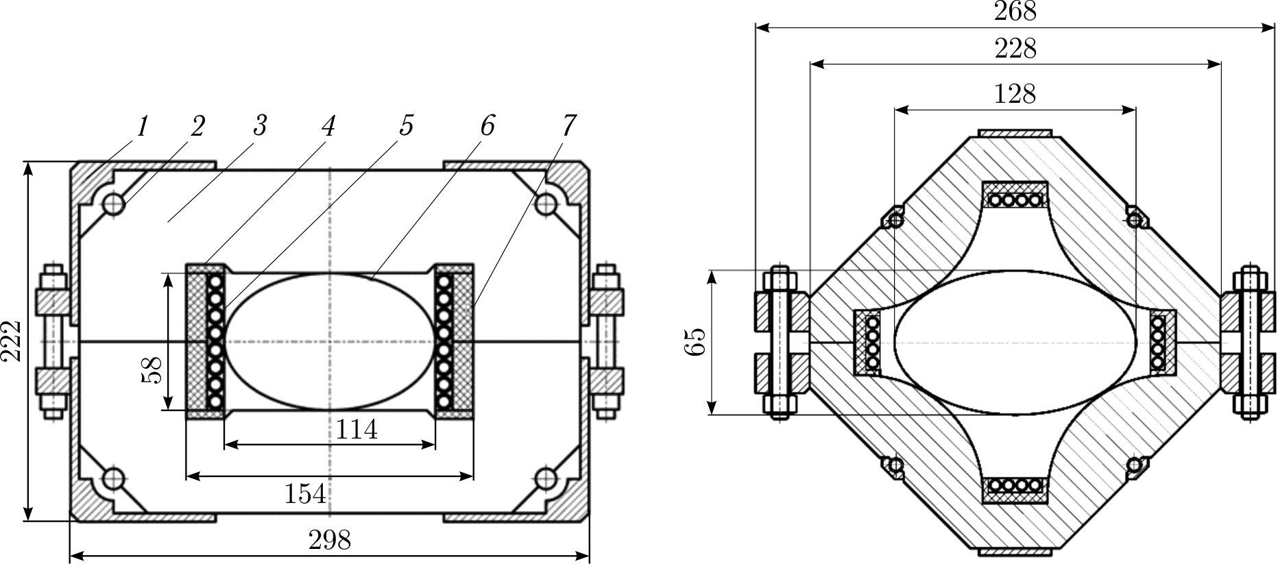
Figure 24. Cross-section of the dipole magnet (left) and quadrupoles (right) of the New Nuclotron with combined cooling: 1 — corner; 2 — yoke cooling tube; 3 — yoke; 4 — end spacer; 5 — winding; 6 — beam chamber; 7 — side spacer.
Based on a large amount of experimental data on heat release in the iron yokes of the Nuclotron and NICA Booster magnets, we have estimated that the power of dynamic heat release in the yoke of the NN dipole magnet (with combined cooling, 2.88 m long) does not exceed 10.3 W. Taking into account the static heat load to the yoke from the environment, we obtain that the heat load to the nitrogen from the magnet will not exceed 40.3 W.
Dynamic heat release in the winding consists of energy losses due to eddy currents in the cupronickel tube, as well as hysteresis and eddy losses in the superconductor. An estimate of the maximum dynamic power of heat release in the winding of the dipole magnet, made on the basis of experimental data, yields 2.2 W when the NN operates with present accelerating cycle of 7 s. Taking into account the static heat influx to the winding from the yoke through the insulating spacers, the heat influx to the helium in the magnet will be about 29 W.
Figure 25. Schematic diagram of a magnet with combined cooling by flows of gaseous helium and boiling nitrogen: 1 — superconducting winding; 2 — supply collector with liquid nitrogen; 3 — outlet collector with gaseous helium; 4 — yoke cooling tube; 5 — supply collector with gaseous helium; 6 — outlet collector with nitrogen; 7 — thermal insulation of the winding from the yoke; 8 — iron yoke of the magnet.
The expected heat load on the cryogenic system of the New Nuclotron accelerator will not exceed 2.8 kW at a temperature of 50 K and 3.8 kW at a temperature of 80 K. That will reduce the power consumption required for cooling by at least 10 times compared to the existing Nuclotron magnetic system.
9. Conclusion
For 50 years, VBLHEP JINR has been developing and researching superconducting magnets for charged particle accelerators. In 1993, the Nuclotron SC synchrotron was put into operation; in 2012, magnets for the SIS100 synchrotron (FAIR project) were put into serial production; in 2020, the NICA Booster cyclotron was put into operation; in 2025, it is planned to launch the NICA collider, a 3-MJ energy storage device based on HTS material and the MSC-230 medical cyclotron; successful research is underway on model magnets for the HIAF and New Nuclotron projects. These developments are in high demand and are widely used in many laboratories around the world.
Conflict of Interest
The authors declare no conflict of interest.